Arduino Car Counter
While talking about electronics at work, my colleague mentioned a car counter he’d bought for a large sum of money that never really worked. I had the idea that I could build one myself, from Arduino, and thought I’d give it a try.
In 2019 when I did this project, internet searching found the following projects that I used as inspiration:
- Arudino people counting, using PIR (passive infra-red)
- Kris Temmermen’s car counter on Hackaday
- Plus a couple more that are now gone and only available on internet archive: makercave, and tomorrow-lab which doesn’t have all the files any more. All of these sites were incredibly useful, both for ideas, inspiration and code help.
The plan was to use a pressure sensor to record when there is a change in pressure inside a sealed rubber tube, such as when a car drives over it. Simple! I wanted to make it as low-power as possible, so it would run for a good while before needing batteries changed. It’s to be deployed in a rural location, counting cars coming in and out of a car park.
You can find the arduino code and details of the project in this repo.
Main Kit:
- Arduino Pro Mini 328 - 5V/16MHz
- MPX5100DP Pressure Sensor
- RV 3028 RTC Breakout
- SparkFun Level Shifting microSD Breakout
- 4mm internal diameter rubber fuel hose rubber hose, 4mm T connector, 4mm double headed bulkhead connector
- Weather-proof housing
- A power source
- Connectors and soldering iron
The car counter uses Arduino Pro Mini, a great, compact, low power arduino. However, it doesn’t have a USB socket, so power needs to go straight to a pin, carefully, and it needs an FTDI board to convert USB to TTL, or something similar, so it can be programmed. It also has offset A4 (SDA) and A5 (SCL) pins. This is a pain when using a breadboard because they don’t line up with any holes. The trick is to solder them to A2 and A3 respectively, turning those pins into SDA and SCL.
- The RV3028 RTC is a great low power clock module. It’s I2C; it connects to the SCL/SDA.
- The microSD card breakouthas SPI connections, CD, DO, SCK, CS and VCC and GND.
- The Pressure sensor, the NXP MPX5100DP connects to 5v, GND and an analogue data pin - I used A0.
Cars run over a sealed rubber tube on the ground, which is connected to a NXP MPX5100DP pressure sensor. The rubber hosing was sealed at one end (I used the T-connector in the end of the hose, and a short length joining the two arms to the T, making it sealed) laid across the entrance to the car park and fixed in place with saddle clips, which were screwed into rawl plugs I drilled in the road. Drill a hole in your housing and use the bulkhead connector to get the tube inside and connected to the pressure sensor - see image below for how I did it, using a short length of 4mm plastic tube I had lying around to go from the bulkhead to the pressure sensor once inside the housing:
Connecting it up:
You can connect up the Clock (RV 3028) and the microSD card breakout as normal. The pressure sensor - MPX5100DP - has 6 pins. Pin 1 is notched, and connects to any pin. Pin 2 is ground and pin 3 is VCC. (NXP, who make the pressure sensor, have a surprisingly active and helpful online forum).
The pressure sensor works by measuring the pressure in one of the ports, and comparing it to the pressure in the other port. The difference is returned as a voltage between 0 and 5. This can then be converted to Kpa or mb but we don’t really need to know that, so we’ll just use the raw values the pressure sensor returns to us.
Code
I made two code files, one for calibration and one to run. You can find them on my github. As cars are all pretty much the same weight (“heavy”) when compared to a human or an animal, this let me see what that was, so I could set the pressure level at which to record a car.
The second code waited until the reading from the pressure sensor reached above a certain amount (worked out from the above) above the average of the past twenty readings. Changes in air pressure and temperature could affect the pressure in the tube, so an average is used instead. It measures a data spike, and it waits 400ms between readings. It writes this “hit” to the SD card with date and time.
Housing
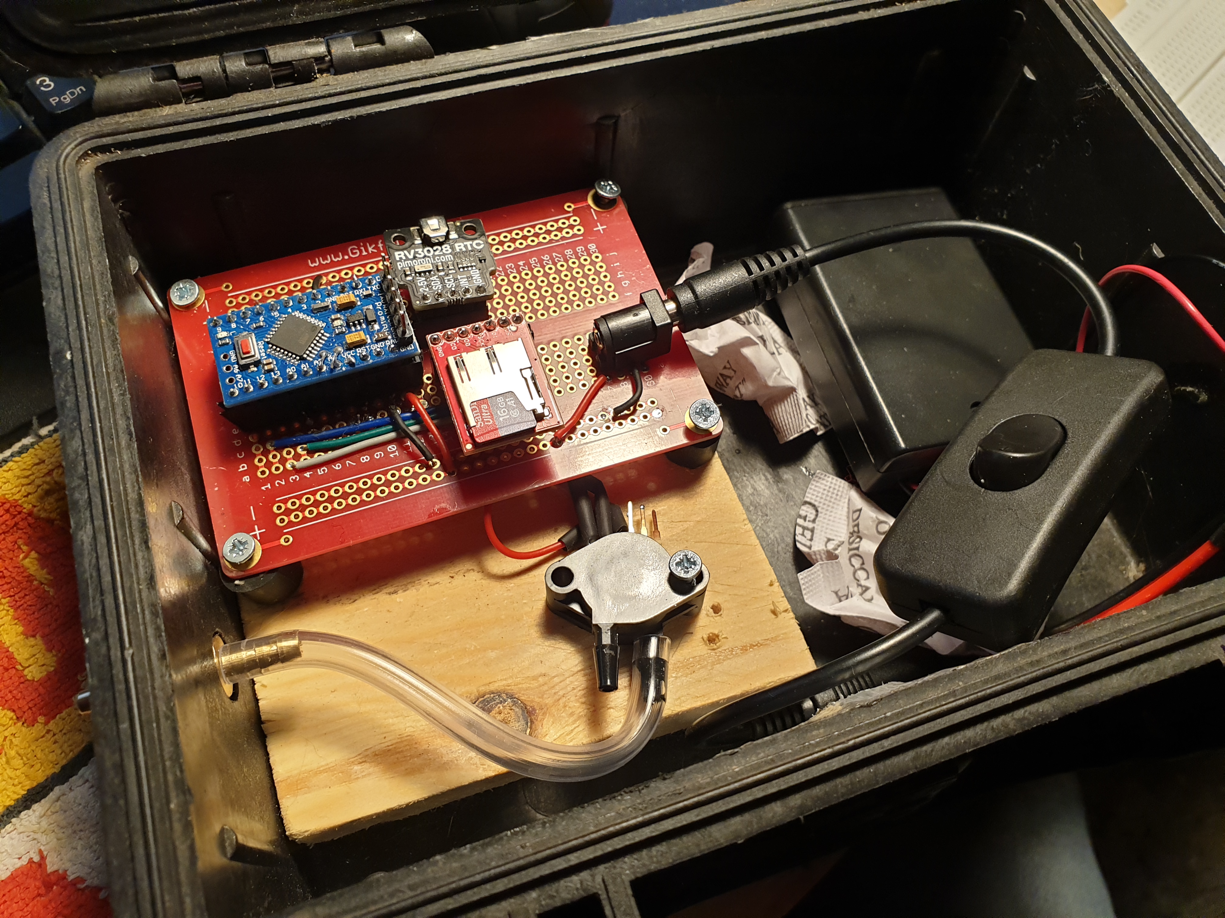
Using a pelicase clone and a bulkhead connector, I was able to house everything in a nice waterproof unit. I added solar power with an energiser and a small solar panel.
Testing and Calibrating
With the first code running, I drove a car, a pickup truck and finally I jumped on it a bit, then looked at the results graphed. This showed that the average time between each axle of the vehicles was 0.345s, and anything above 60 was probably going to be a car.
I regularly checked the results and tinkered the calibration to get it right. Obviously, the number of vehicles counted needed dividing by 4 (Two hits for each car, and each car enters and leaves the car park).
Power Consumption
I didn’t have a way of measuring low power, but I calculated the power consumption from the components as using 193mA when triggered, and 11.3mA when at rest. I had it running for 147 hours off 1900mAh batteries (12mA average), but there weren’t many cars to trigger it. There are loads of ways to further reduce power consumption of an Arduino pro mini (see https://www.gammon.com.au/power), but this was low enough for me to power it with a small 12V battery or a few lithium cells.
Future Ideas
This was simple to set up, and for under £100 I was able to not only accurately count the numbers of visitor’s cars to the reserve, but the different numbers on each day and even time of day.
The first obvious improvement would be to implement a sleep function to save battery. And now it’s a few years on, I would absolutely use ESP32 for this project, and have it send the data somewhere rather than (or as well as) save to SD card.
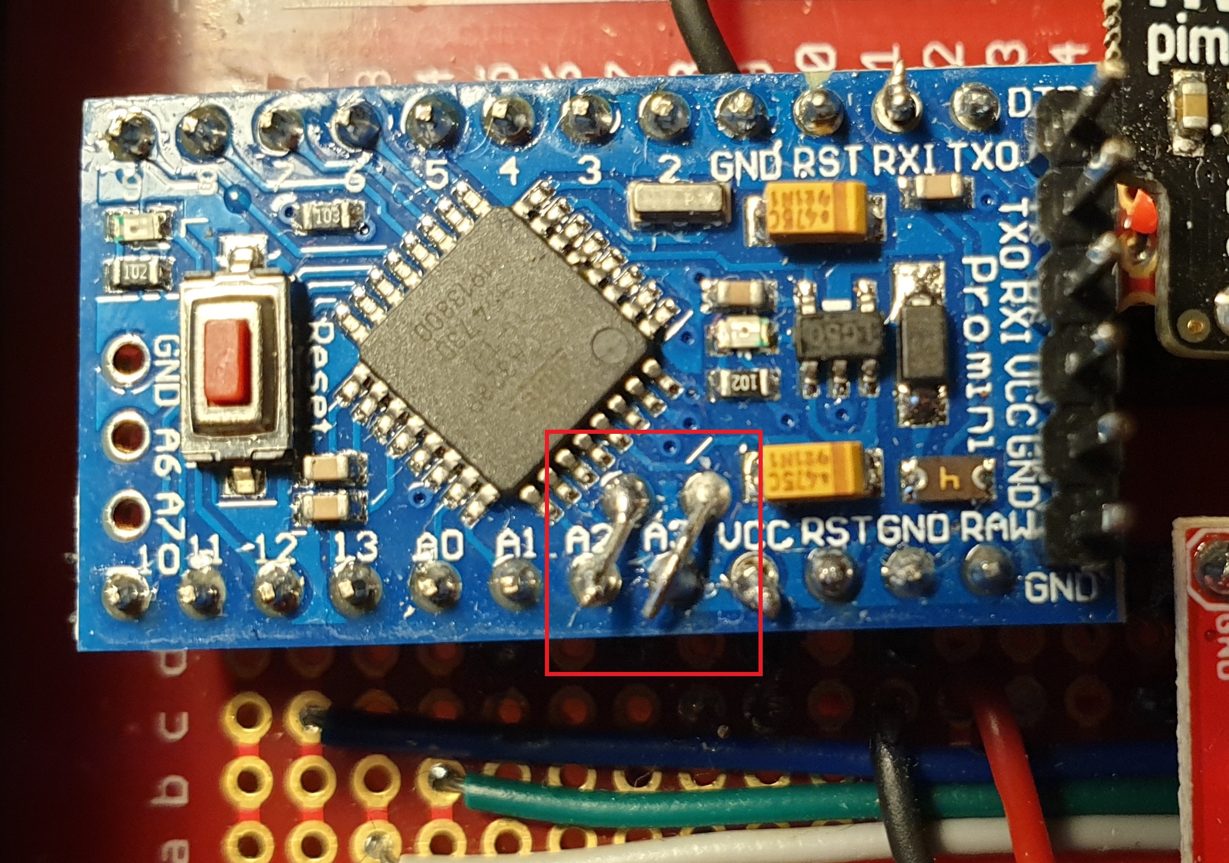 Connecting up SDA and SCL to pins A2 and A3
Counter tech in the box, powered by batteries and with an on/off switch
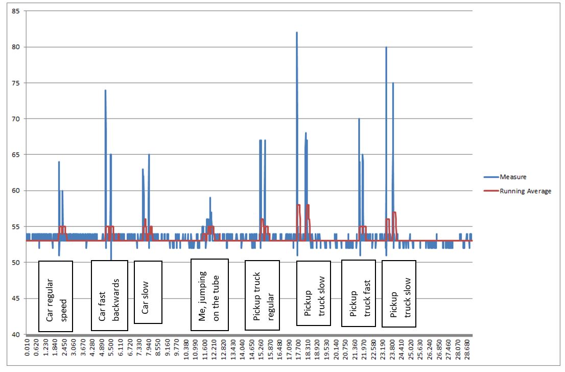 Example of calibration graph